Readers: The signals and signal systems that I will be reviewing and installing in my Layout How To series were provided at no cost by Azatrax LLC. However the selection, installation, operation, and opinion of these signals and systems are 100% my own.
 |
| ABS Intermediate Signals east of Bay City |
 |
Backstory
The St. Clair Sub is a "DTC" (Direct Traffic Control) dispatched line via dispatcher issuing specific blocks to trains which represents track authority. DTC as modelled is currently used by the Alaska Railroad. This segment of the railroad had never been controlled by a signals in my freelance world but has some of the highest daily train counts on the system. With rail traffic in this corridor showing strong future growth the State and Michigan Interstate Railroad decided to signal Bay City to Port Huron, roughly 100 miles. Once installed the modernized "ABS" Automatic Block Signal system will be a safety overlay for the existing Direct Traffic Control dispatching in addition to locomotive GPS receivers, and train crew remotely operated sidings.
Overview For some time I have always been awe struck by the complexity and uniqueness of signal systems that control North American railroads. No signal system is exactly the same while they all follow similar basic concepts. Even more impressive are model railroads who implement signal systems in a prototypical manner. Knowing that these systems can be costly, expensive, and complex I have always been intimidated and found the cons to outweigh the pros. Fast forward to some ops sessions ago when someone had asked "Signals in the future" so it got me thinking again and this time I was looking for a system that was easy to setup, modular, but still very prototypical to fit plausibly on my class 2 regional system. Searching the pages of a Model Railroader one afternoon I discovered Azatrax and the TS2 Block Signal circuit which met all of my requirements. Conversing with John Parsons the owner my questions were answered and fear of installing extinguished. If I can install this system over small evening work windows or on a Saturday so then could others have an opportunity to add something similar on their own railroad. The TS2 Signal Circuit from Azatrax is really a great product for any size layout including free-mo and modular setups because it is designed to operate by itself in virtual mode or in concert with any number of TS2s connected together creating an automatic block signaling system. That being said lets talk more about benefits and limitations of the circuit. 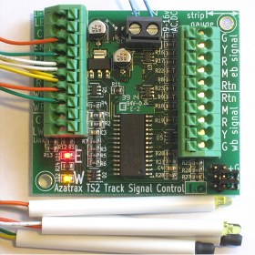 TS2 Signal Circuit and sensors - Courtesy Azatrax LLC. Circuit Benefits:
Detection at block boundaries for the signal circuit are handled by an east and west pair of IR LED lights / receivers. When the IR light reflects off the bottom of the locomotive or rolling stock and is caught by the receiver it indicates being occupied. We will look behind the scenes of the detection install and testing in our next post where we install TS2 #1, signal 1, and signal 2.

IR LED light reflect off equipment and caught by receiver sensor - Courtesy Azatrax LLC

Example of sensor placement with signals for a single block - Courtesy Azatrax LLC.
For folks with double track mainlines that run directional, Azatrax offers a TS2-D specifically designed to handle directional running. The install concepts from my bi-directional signal track install can be applied to the directional double track as well. If you want to look at the TS2 or TS2-D in more detail, I have provided a link to it directly on Azatrax's website. http://www.azatrax.com/block-signal-circuit.html

Diagram showing the modular connectivity of the TS2 circuit - Courtesy Azatrax LLC.
Planning
Undertaking any large project like this requires a plan to stay on task and complete in a timely manner, Since the TS2 has different capabilities such as independent mode, connected mode, and interlocking functions its important we cover these so you the reader can see if this system would work for all or maybe a certain section of your railroad. Progressing through each phase the basic install will not change nor will the circuit but we will build upon each phase to showcase all of the functions step by step. When complete in October the layout will have ABS signals protecting from East Staging to Bay Yard and you the reader will have an online guide to help understand this products features and how you can install and use it. Starting with this post we will spend the next four posts installing wrapping up with a recap and operations post.
Part 1 (Project Overview / Planning) - Early August
Part 2 (Phase 1 - Single TS2 with Virtual Blocks) - Mid August
Part 3 (Phase 2 - Connecting Multiple TS2s) - Late August
Part 4 (Phase 3 - TS2 Basic Interlocking) - Mid September
Part 5 (Phase 4 - TS2 Advanced Interlocking ) - Early October
Part 6 (Project Recap / Operations) - Mid October
The signal diagram provided at the top of this post shows graphically the DTC blocks, detection locations, signals, and install phases so you can follow along, Each post will include a diagram for the specific phase being installed in further detail.
We will kick off the install posts next Wednesday with Phase 1 - Single TS2 with Virtual Blocks install. In this post we are going to install the sensors, TS2 circuit, test, install the signals, and operate in independent (Virtual) block mode. Appropriately these posts will be picture heavy to better describe each installation step.

Westbound signal entering Bay City (Bay Yard) interlocking around curve.
Approaching an exciting Layout How To series.
Check back next Wednesday for Part 2.
|
Initially I don't see an application for this on my home layout as most of what I model had no signals and traffic density is light. I could probably implement some signals though if I wanted.
ReplyDeleteBut your mention of Free-mo got me thinking about my module. Signals are cool of course, and my module is basically a freelanced implementation of a prototypical track arrangement. It lets me do things I otherwise don;t do on the layout.
It features a main with passing track. Being able to indicate an open or occupied block at each end of the module would be a neat thing to add to the module, so I'm going to keep following your series and think about an implementation there. I know there is an overriding Free-mo signal standard, but being a closed system that does not integrate to the bus would make it an easy application within my module. Thanks for sharing!
Thanks for the feedback Mike, stay tuned for updates showcasing multiple blocks working together and interlocking features. It is amazing how just the two signals (one each direction) have added so much life to the layout.
ReplyDeleteGM