
Wednesday, August 31, 2016
Wednesday, August 24, 2016

Wednesday, August 17, 2016


Thursday, August 11, 2016
St. Clair Sub Signal Install - Part 2 (Phase 1 - Single TS2 with Virtual Blocks)
Readers: The signals and signal systems that I will be reviewing and installing in my Layout How To series were provided at no cost by Azatrax LLC. However the selection, installation, operation, and opinion of these signals and systems are 100% my own.

Circuits and signals arriving from Azatrax
MATERIAL INVENTORY
Getting started lets take an inventory of the ordered components:
1 - Azatrax TS2 Circuit
(Kit includes the board, 2 sets of IR LEDs and IR Receivers with wire leads)
**Note for this specific part 2 install we will not use the 1,000 ohm resister**
1 - Azatrax PS906 9V Power Supply
1 - BLMA 1038 Block Signal
1 - NJ International 1071 Block Signal
In addition to the ordered components, you will the following items:
- 3/16 inch #12 Drill Bit
- 3/16 inch #12 Drill Bit
- Small Wire Stripper
- Solder Iron / Rosin Core Solder
- 28 Gauge Wire - Solid in at least three colors
- Signal Tester (Used for BLMA signals which are made with magnet wire)
- Heat Shrink Tubing
- Hot Glue Gun


TS2 Circuit, IR LEDs wired, IR Receiver wired, and resistors
Directions for installation of the Azatrax TS2 can be found on their website. My install will follow those directions, which you must do during this install..... no shortcuts or going rogue!
SENSOR INSTALL
Before touching your layout - first read the directions provided with the product.

Before touching your layout - first read the directions provided with the product.

TS2 Instructions.... please read them
Once directions are read you will want to identify where to locate your sensors and signals. Iinstall your sensors around 40 to 50 HO scale feet apart with the signals centered between. For this I used a Roundhouse covered hopper to help get me the spacing needed.
 |
| The center of my sensors will be located under the truck centers of this railcar. |
 |
| Diagram of sensor / signal placement - Courtesy Azatrax LLC. |
Once you know the location you can then use the drill bit to create the hole for the sensor. When starting out I turn the bit by hand getting through the ballast and part of the plastic tie. Once into the benchwork I then connect the bit to a power drill to get through any wood. Key is take your time and keep the drill speed low.
 |
| Drilling the first hole |
 |
| First two holes drill - I stuck two ties into the hole to show angle for the sensors. |
Like with any project it takes time to get the process down. In the case of drilling holes I originally have two ties in between each sensor. After testing and working with John Parsons it was found for HO scale the best practice is only having one tie between sensors.
 |
| Threading the IR receiver through hole. |
 |
| IR receiver almost installed. With a 3/16 bit the fit is very snug. You may need to twist as you push the final portion just below tie level. |
 |
| IR LED (Left) and IR Receiver (Right installed)
The same process is followed for the other pair of sensors on other side of signal.
As you can see there are two gaps between sensors. After testing I had to redrill the IR LED one space closer to the IR Receiver.

Changes made - the IR LED (Right) moved one tie space closer to the IR Receiver (Left). The large hole to the left where the original hole was located will be filled with hot glue and covered in ballast after sensors are tested.
CONNECTING SENSORS TO CIRCUIT
Following along the TS2 directions we next need to connect the orange, white, yellow, and green wires from the installed sensors to the circuits. This process is very easy as each wire whether east or west sensor has its own color and specific terminal block to connect with. The TS2 is equipped with "spring cage" quick connects so using a flat head screwdriver makes install quick and easy.
 
Following directions first connect the east sensor pair then west sensor pair.

Layout of TS2 board with sensor links on left, power on top, and signal connections on right.
Courtesy Azatrax LLC.
At this point before you install your signals you need to first ensuring your IR LED / Receivers are paired properly. Double check this before connecting power to your TS2.
Once power is connected from the power supply to the P1 and P2 locations on the circuit it is imperative that you test the accuracy of your sensors.

When i made the install i tested with sensors spaced two rail ties apart which worked ok for railcars but the angle was off for sensing locomotive fuel tanks. I went back drilled new holes and move the IR LED one rail tie space closer. SUCCESS!! With this small adjustment the IR beam was properly reflecting on all types of railcars and locomotives.
SENSOR TESTING
Using different types of railcars and locomotives test each of the sensors. First test the east sensor by rolling a car over top of it. Then test the west sensor. While the car or locomotive is above the sensor they should light. If not adjustments would need to be made. The directions provide scenarios for troubleshooting, If you still have issues reach out to Azatrax. John was very helpful with the sensor troubleshooting due to the tie spacing. Provided are photos of what the sensor lights on the TS2 should look like when you are testing and during operation.
 
East sensor lit only - this should only be on if a railcar/locomotive is on the east sensors.
Before continuing to signal install, ensure your sensors work correctly first.
SIGNAL PREP / INSTALL
For this install we will be using BLMA and NJ International three light signals. These are LED signals with a common wire setup. Another great feature of the TS2 is flexibility to handle many different types of signals and be polarity smart for the signals. The directions display how to connect wires for many different configurations. But before we can connect signals to the TS2 we need to extend the wire leads on both signals.
 Once labelled solder on wire extensions and heat shrink the connection. For the installs red is red, yellow is black, green is green, and common is red with black dashes made by the sharpie.    To complete placement I use white glue to secure signal base to surrounding ballast. You can see the glue at the signal base which will dry clear. 
Following install directions on the TS2 instruction sheet connect each signal wire to its proper location. Refer to the instruction sheet as different signals require different connections. Azatrax did a great job providing just about every example on the instructions to help install very easy.
With the signals installed and wired I take a break and let everything dry versus continuing to work and potential dislodge a signal. At this point everything is in place and your sensors work correctly. Once everything dries we can see the whole package work.
JUMPER CONFIGURATION
Before we flip on the juice to the power supply there is one item to decide... Three Aspect or Four Aspect signal operation. You can check out my blog post from Tuesday 8/9 or my YouTube page (search: Azatrax TS2) to see the signals operate in both configurations. On the MCIS we will be operating in four aspect configuration (Stop, Approach, Advance Approach, and Proceed).
To change from three aspect (factory default) to four aspect all you need to do is move the jumper from right to left.

Diagram of jumper - upper two are for yellow adjust on searchlight signals. On this post we are focused on moving the jumper on the bottom set. We will move it from covering only the right pin to covering both the left and right pin.

The jumper setup from the plant. This is TS2 installed in this post.
Using tweezers pull the jumper off and then put it back on covering both the left and right pin. There you have it the TS2 will now operate in four aspect signal configuration.
TS2 OPERATION
Flipping on juice to the power supply the TS2 comes alive. Remember this system operates independent of your track wiring bus or DCC system. Once on the signals for the TS2 will display "Approach" since the system does not detect resistor wheelsets. I work around this by operating a small three car train over the railroad with yellow signals. Once this train is detected the signals will sync up to green and then operate in their four aspect configuration.

Westbound signal at East Bay at startuo

Eastbound signal at East Bay at startup
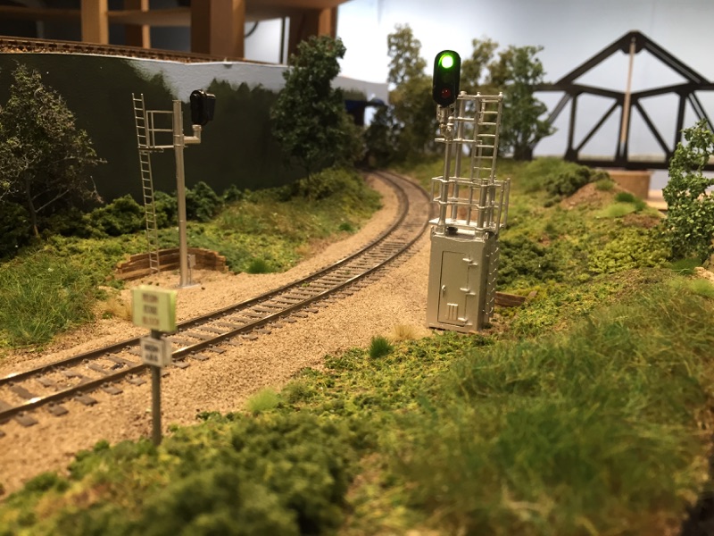
Post startup train - signals have synchronized
At this point the signals and TS2 are ready to enjoy. Just remember that when you finish operating on your layout that you turn off the power to the signals since they are independent of DCC Bus.
Once satisfied that everything from sensors to signals are all working, you can then re-ballast your track if installing in an already sceniced area.

Ballast added over former drilled holes and around the sensors. Only 1 to 2mm of the IRs need to visible so use scotch tape to cover them while ballast / gluing. Afterwords using a dental type pic you can remove the tape and your scene is finished and operational.

West sensors scene end result

East sensors scene end result
Wrapping up your ballast of the scene you have completed and finished your install of the Azatrax TS2 Signal Circuit and two signals operating in virtual four aspect configuration. I hope you have enjoyed this install, please check out videos of the signals operating to see the potential this product could bring to your railroad. Thank you to Azatrax for providing the products and support in making this install successful. Later this month we will continue adding more TS2s, signals and then connect them to work together.
Regards,
GM
|
Tuesday, August 9, 2016
ABS Signal System (Three / Four Signal Aspect Demo)
Well my model content is going video now... Take a look at operation of the Azatrax TS2 Model Railroad Signal Circuit Controller in three and four aspect operation. Tomorrow evening I will be publishing on how I installed this circuit, sensors, and signals.
Readers: The signals and signal systems that I will be reviewing and installing in my Layout How To series were provided at no cost by Azatrax LLC. However the selection, installation, operation, and opinion of these signals and systems are 100% my own.
Video quality is ok - working on improving this with future videos. Luckily you can still see the signal aspects changing.
Readers: The signals and signal systems that I will be reviewing and installing in my Layout How To series were provided at no cost by Azatrax LLC. However the selection, installation, operation, and opinion of these signals and systems are 100% my own.
Three Aspect Operation
Four Aspect Operation
Monday, August 8, 2016
Early August Update
I continue to suprise myself during the install of ABS signals on the "Clair". Just when I think my focus is diverted from normal updates, I find that signal progress causes other items to be completed creating content for you the viewer. This update will be quick but very relevant to the ongoing work.

 Backdrop painted with grasses being added.
 Final scene turned out very nice.
 Heki Wildgrass 1577 that installs with white glue. It can stretched very thin or left in larger clumps.
 Scenic materials have come a long way from when I was a teen. These are long tufts from Mininatur.
 Center picture - scenic briar patch mat from Scenic Express.
 Ready made trees from Timberline Scenery and ready to make SuperTrees.
 Signs you have been familiar with... DTC signs at block and switch boundaries along the Clair. Aka: Toothpick wonders
 DTC / ABS sign combined. Originally the DTC signs were mounted on toothpicks. As scenes are completed I remount them to scale sized posts.
 Speed limit just east of Bay Yard heading towards Upper Huron / Port Huron.
 Temporary crossbucks in Upper Huron.
 Blair Line signage used as basis for MCIS whistle boards, derails, speed limits, and begin / end ABS. MCIS standard calls for 90' corners and are box, diamond, or rectangle in shape. DTC signs are high visibility green with black lettering. The other balance of signs are black font on white backgrounds.
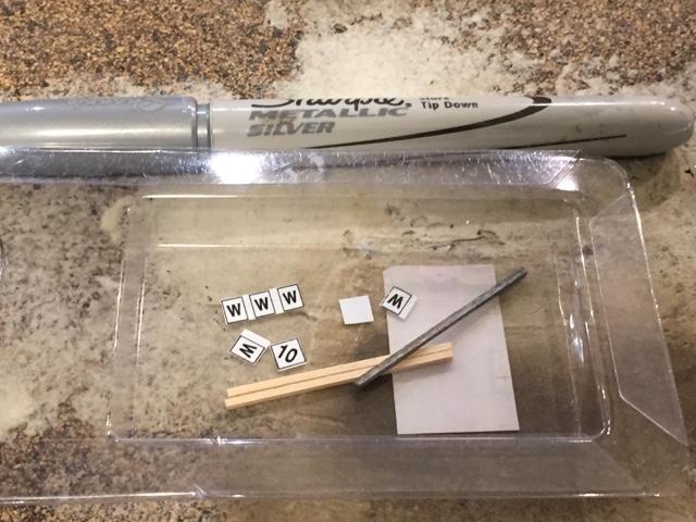 Once cutout I use a silver sharpie to color the sign post before using a small dab of CA to afix on post.
 Finished DTC-ABS and speed limit signs. Four signs down... Plenty to go.
 A very new and clean BNSF no trespassing sign on the side of a grade crossing bungalow. Modeling opportunity you bet - using Word and paint on the computer you could scale this down, print on paper, and afix to bungalows or as a sign along the right of way.
Preview of Progress at East Bay as L-PBBA-05 returns to Bay Yard from Port Belle.
Scenic Refresh @ East Bay
Prior to the signal install I cleaned out a lot of scenery elements like bushes and trees since they could get damaged in the signal install. More importantly this area needed a refresh. With signals installed and operating here, I spent some time over the weekend added back grasses, ground cover, and trees. Additionally I took a whirl at painting a simple backdrop to represent distance trees using craft paints. The backdrop when paired with trees and scenery looks pretty good.
The key on scenery in my opinion is having lots of product variety and layering. Add some, take a break let it dry and the add some more. Like my good friend Shannon Crabtree I prefer to do my scenic gluing and work at night. (Be sure to check out his recent video posts). While I sleep it dries, then in the morning you get to see the end result. Scenery is a forgiving process, but it takes time and lots of practice. Sometimes you just have to jump in and give it a shot, you will surprise yourself.
Right of Way Signage
One detail overlooked a lot is signs along the railroad right of way. When you stop and look there is a lot more than just track and vegetation. A great resource I refer to often is the How To Build Realistic Layouts "Trackside Scene" special edition. This book has an article about right of way signs, examples, and product list in HO scale. Each railroad has their standard style including MCIS so let's take a look along the right of way.
A very new and clean BNSF no trespassing sign on the side of a grade crossing bungalow. Modeling opportunity you bet - using Word and paint on the computer you could scale this down, print on paper, and afix to bungalows or as a sign along the right of way.PSA: (In no way should you ever trespass on railroad property or right of way to get photos or sign ideas. This is dangerous and illegal.)
Well there you have it progress from well progress. I imagine as the signal project gets more advanced these type of extra strides may be less, but any progress you can make on your layout should be celebrated as a success. My guest and regular operators along with myself will appreciate the detail. Later this week I will be posting my Part 2 ABS Signal Install post so be sure to check back soon.
GM
Subscribe to:
Posts (Atom)