Showing posts with label Azatrax. Show all posts

Tuesday, October 18, 2016

St. Clair Sub Signal Install - Part 5 (Phase 4 - Advanced Interlocking)

October is here and with it brings our next phase of the St. Clair Sub ABS signal system install. This post we will walk through Advanced Interlocking at the Grays Lake West Siding Switch (WSS). Using the concepts we have learned through our previous posts we will connect three signals with the TS2 circuit and a Blue Point Turnout DPDT switch.


Readers: The signals and signal systems that I will be reviewing and installing in my Layout How To series were provided at no cost by Azatrax LLC. However the selection, installation, operation, and opinion of these signals and systems are 100% my own. 

Eastbound signal at West Siding Switch (WSS) Grays Lake installed

Kicking off this phase like we have with all in the past, it is important to first read the directions, lay out your materials, and have all of your tools. This install requires the same tools from Part 4 - Phase 3 which has been consistent since our first block. Following Azatrax's instructions both of the sensors for the dual head signal need to be located prior to the switch. 

SENSOR INSTALL

Courtesy Azatrax LLC.


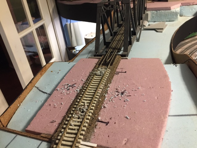
 Marking the location where sensors will be mounted prior to drilling holes

Looking up from lower deck - holes for signal and TS2 sensors. 

 Installing IR LEDs first between the concrete ties

 Installing IR Receivers next through tracks. Note the angle of the receivers and LEDs is key

The end of the LEDs and Receivers can be gently bent a little to get the correct angle. 

IR sensors installed (location noted by fingers) ready to connect to TS2 and test 


 Wires from sensors fed through foam board. 

Until the final connections are complete I use blue painters tape to hold the wires in place keeping all the wires neat and organized. 

 Wires connected to TS2 - testing with multiple types of cars and locomotives.

Before moving beyond this step - ensure the sensors detect properly. Refer to Azatrax directions for troubleshooting, adjust sensors as necessary, test until it is right.

SIGNAL INSTALLS


Once your sensors install is complete and operating properly, we can turn our attention to adding signal to the TS2. For this block we will install a dual head BLMA (right hand) signal and two BLMA block signals (one right hand and one left hand).


 Signals pre-wired and staged at Bay Yard ready to install

Wiring signals before installing on the layout helps tremendously with time savings and frustration factor. I used 22 ga. wire for the signals in this project and probably could have gone a tad smaller but this size seemed very durable.

 Threading the wires through the foam board. Use painters tape to band the different signal heads together prior to install. 

 Instead of trying to take pictures of connecting the wires I figured it was best to provide step by step guides on how to connect all three signals and make them operate as planned. 

Step 1 l is identical to how we have installed signals on all of the previous blocks with a east and west signal.

 Sensors, Eastbound, and Westbound signals connected to TS2 board.
Step 2 we dive into the advanced interlocking. By connecting signals #2 and lower head of signal #1 to the DPDT we are able to drive the signal aspect to either be red or green depending on how we have thrown the switch which drives the Blue Point turnout controller. The DPDT could easily be a Tortoise type machine. 

 View of Blue Point Turnout Controller with wires soldered to connections below.
 Step 3 uses the concepts from basic interlocking in our last post using the 1000 ohm resistor to cause the TS2 to sense a detection. This happens when the switch is thrown the DPDT routes the power from #6 to #4 where resistor causing a detection. Once these connections are complete spend some time operating the signals and running trains through them before connecting with TS2 #5 at Upper Huron. 


 Using switch knob on fascia to move throw switch and test DPDT / signal operation 

View of TS2 connections between TS2 #5 and TS2 #6. Using plastic clips to hold TS2 power cables and (LE to LW) and (C to C) wires.

Overall view of West Siding Switch at Grays Lake

WEST SIDING SWITCH OPERATIONS

The following diagram below describes signal operations at the west siding switch using the TS2 and DPDT switch. It is important to remember that this is not a CTC control point, the signals do not convey authority to enter main track. 

- Upper head of eastbound and westbound mainline signals are ABS intermediate signals
            These signals indicate block occupancy only or if switch is thrown against mainline

- Lower head of eastbound and westbound signal siding signal display switch position only
            Red - signal lined normal for mainline
            Green  - signal lined reverse for siding

Direct Traffic Control blocks issued via dispatcher provide authority to enter to operate over main track. 


Proceed indication with next two blocks clear / Switch lined normal

 Approach indication with next block at Gerhard occupied  / Switch lined normal

Stop indication due to caboose just traversing into block / Switch lined normal 

 Switch thrown against mainline within in block / Switch lined reverse to siding

Westbound signals - Left signal for siding (switch indication) / Right signal indicating block occupancy 

With the westbound siding switch and signals operating, I am now wiring up the eastbound siding switch and signals. These signals will operate via TS2 Circuit #7 prior to the mainline going into east staging. Beyond the detection circuit at the east switch one more TS2 #8 will be installed just ahead of the east staging yard throat. This final circuit will provide proper advanced block occupancy indications whether operating east or west. 

I hope you have enjoyed this install post. For me it did stretch my wiring abilities where I learned how to tackle more complex wiring. Breaking it down into smaller steps really helped bring it all together. While it is not a CTC control point, the ability for the TS2 to drive four signal heads at a siding can allow you to have an effective signal system with ABS as the basis. With our DFW Interchange session coming up next weekend, the system will add another layer or railroading for the operators. Please feel to ask questions about the install, one of my goals with this series is showing that you can add this type of setup to your railroad. 

GM 

Friday, September 30, 2016

Upper Huron Wye Signal Operation

On Wednesday we discussed the installation of the TS2 signal circuit along with process to allow interlocking operations. Tonight we are going to walk through the operation of the interlocking function at Upper Huron. 

Readers: The signals and signal systems that I will be reviewing and installing in my Layout How To series were provided at no cost by Azatrax LLC. However the selection, installation, operation, and opinion of these signals and systems are 100% my own. 

Operations 

Our example train the R-GEPB-29 (Road Switcher Gerhard to Port Belle of September 29th) led by MCIS 3833 has be issued track authority by St. Clair Sub dispatcher to proceed from mainline DTC Block Lacey (LACE) to DTC Block Upper Huron Jct (UJCT) via Upper Huron East Wye Switch (EWS). 


Upon reaching the signals / block boundary at east wye switch Upper Huron, the train comes to a stop and the conductor climbs down to change the route. 

Reaching the signal mast, the conductor opens the control box and pushes the button "Press to Occupy". 

The operator throws the Peco switch from normal to reverse to the east leg of the wye at Upper Huron. 

The operator acting as the conductor in reality pushes the "Press to Occupy" on the panel. This action shunts the signal from a "clear" to "stop" indication. 

With signal indicating the east switch at Upper Huron block is now lined reverse and authority given by dispatcher to occupy the UJCT DTC block, R-GEPB-29 proceeds onto the east leg. 

Train departs past the signals and operates onto the east leg of the wye which ties directly into the Port Belle Sub.

Once the train is in the clear onto the Port Belle Sub the conductor uses the north end control box where the east / west wye legs come together to line the switch back to normal and clear the signal. 

With the train on the Port Belle Sub our TS2 system does not know this as it expects to either see the train reverse over the sensors at the east switch or continue over the sensors at the west switch. Since we are doing neither, we hold down the "Press to Reset" button which clears the block back to green.


At this point once the operator has verified signals display "clear"and switch is re-lined the R-GEPB-29 continues on its journey. The abs signals at the East Wye Switch stand ready for their next use.

The same process happens coming from non signal territory to signal detected territory with the exception that instead of pushing "Press to Reset" after lining the switch back to normal, the operator would simply push "Press to Occupy" again. This has to do with the train coming onto signal'd territory so the system knows there is a train occupying an actual block in signal territory versus our example above where the train left the signaled territory requiring us to manually clear the block. 

This is a very simple example of using the interlocker ability, one example to automate further would be having the "Push to Occupy" button drive a tortoise motor which act as the SPST Off-On driving the TS2 to change the signal. There are plenty of other examples of ways to use this function such as a drawbridge. Take a look at the Azatrax Block Signal page for more ideas.

The best part of our hobby is the ability to make things as simple or complex as you would like based on your skills. For my setup a simple push button and using my finger to throw the switch was sufficient, and requires operators to engage "beyond the throttle and fascia".

Stay tuned in October for the last few posts of my signal install series. In these upcoming posts we will dive more into Advanced Interlocking using TS2 circuits on a passing siding, and then wrap up with a discussion on how a train would operate in DTC/ABS territory.

GM


Wednesday, September 28, 2016

St. Clair Sub Signal Install - Part 4 (Phase 3 - Basic Interlocking)

Continuing with our signal installation series, in this post we will focus on basic interlocking using the Azatrax TS2 signal circuit. At the same time we will add another signal block to the Michigan Interstate St. Clair Subdivision. 

Readers: The signals and signal systems that I will be reviewing and installing in my Layout How To series were provided at no cost by Azatrax LLC. However the selection, installation, operation, and opinion of these signals and systems are 100% my own. 


If you have been following my signal install series, you probably noticed that each post we build upon the previous. The best part of building upon each phase is the basic process gets easier while we add a new piece that is a little bit more work. 


MCIS 3830 knocking down the signals at east end of Upper Huron. In this post we will walk through the install of these signals, TS2 circuit, and adding the ability to "interlock".

MATERIALS

1 - Azatrax TS2 Circuit Kit
            (Kit includes the board, 2 sets of IR LEDs and IR Receivers with wire leads)
       We will use the 1000 ohm resistor for this install
2 - BLMA 1038 Block Signals
1 - Single Pole / Single Throw Push Button Switch
1 - Momentary Push Button Switch

In addition to the ordered components, you will need the following items:
- 3/16 inch #12 Drill Bit
- Small Wire Stripper
- Solder Iron / Rosin Core Solder
- 28 Gauge Wire - Solid in at least three colors
- Signal Tester (Used for BLMA signals which are made with magnet wire)
- Heat Shrink Tubing
- Hot Glue Gun

CIRCUIT INSTALLATION
We start by marking where we are going to drill for the signals and sensors that will be installed in between the track.

 Signal installation between the east wye switch at Upper Huron and Quinacassee Creek Bridge.

Drilling complete - ready to clean up and begin installing LED sensor and receivers..

Installing the LED sensors through the track is done the same way completed in our part 2 - phase 1 post. It is important to only have one tie space (two ties) between each of the holes drilled at 45 degrees for the sensors. 

 For this install I decided to install the TS2 on the fascia for easy access and maintenance. The wooden box is from Hobby Lobby for around $2.00 and after cutting the back off on a tablesaw, it would fit nicely on the fasica. It is important to ensure plenty of room if you decide to mount the TS2 in a control box.

 Marking the inside outside of the control box I proceeded to drill holes for wire access and TS2 mounting. 

 TS2 installed on fasica, ready to begin fishing wires from LED sensors through from under layout and connect into TS2.

East/Westbound LED Sensor / Receiver and power connected. 

CIRCUIT TESTING 
Test - Test - Test with a variety of equipment before moving on to signal install / connection.
 MCIS GP38-2 #3830 operating at walking speed over the east and west sensors of TS2 #6. Locomotive fuel tanks can cause sensing issues, ensure you test multiple variations and adjust as necessary. 

Intermodal wellcars, tank cars, and covered hoppers put the sensors through its paces.  

Once you feel confident and the sensors properly detect without issue, then it is time to move onto signal install.

SIGNAL INSTALLATION

 Threading the signal wires down through the foam board, under the layout, and through the fascia access holes we prepare to trim down the wires, strip, and connect to TS2.

 TS2 Wiring complete - remember to keep it neat!

 East and Westbound signals at East Upper Huron protecting between the Upper Huron and Lacey DTC blocks. 

INTERLOCKING PRIMER

A quick primer on the function of interlocking at Upper Huron. On each end of Upper Huron is a east and west switch that connects to the Port Belle Sub. When the switch is thrown reverse allowing a train onto either leg of the wye we want the signals on each end of the block to display a "stop" telling the crew that a switch in this particular signal block is lined against the main. In the prototype throwing a switch like this in ABS territory would shunt the signal to "stop", so by using the interlocking function we can represent this same concept. Since the switches are manual, we have to help the system know the switch is reverse and we will do that using the S1 "On-off" SPST switch. Additionally once the train has moved onto the Port Belle Sub and the switch is returned to normal we use the S2 "Momentary switch" to clear the block bringing the signals back to "proceed" indication with the train now in the clear. Remember our ABS signals only display block occupancy, it is still the job of the dispatcher to issue track authority via Direct Traffic Control

UPPER HURON WYE VISUAL

 West wye switch in the town of Upper Huron. The concrete ties are the St. Clair Sub main that heads east to Grays Lake. The diverging track to the left is the wye west leg to the Port Belle Sub.

East wye switch at Upper Huron near the sugar beet plant. You can see the main concrete ties coming around from the west switch and wye east leg diverging to the right. 

INTERLOCKING INSTALLATION

Azatrax provides in each installation guide for the TS2 and online, diagrams for wiring up the TS2 for basic interlocking. In our Michigan Interstate example we have two switches; one for the east leg and one for west leg of the wye. Both switches fall between the TS2 #1 and TS2 #2 so all we need to do is wire in a simple SPST push button switch for S1 and a momentary switch for S2.

In previous installs we have linked TS2s using "LE" to "LW" and "C" to "C". This install is no different as you can see in the diagram below those connections are still there. The difference is the extra set of wires coming from "LE" and "C" on TS2 #1 that split and go to on-off switch S1 and momentary switch S2. This extra set of wires drive the TS2 to operate in interlocking mode between these two TS2s only. 

Basic Interlocking Diagram courtesy Azatrax 

The specific example on the Michigan Interstate. S1 in foreground, S2 in background awaiting wire connections. These were install directly on the fascia using a 1/2 drill bit. 

The extra set of wires to be installed from "LE" (red wire) and "C" (black wire). Using wire nuts to join the wire back to the TS2 (leaving off photo in foreground), wire to S1 (middle), and wire to S2 (background).

Once the wire assemblies were ready, I proceeded to thread the bare wire ends through the switch opening like you would on a decoder. Once wrapped around, I soldered to create a strong connection. Until finished with the wiring i used blue painters tape to hold the wires in place. Permanently plastic holders will be installed. 

Using Microsoft Word I created a simple panel with where the buttons would be mounted along with instructions for operating. Once printed I cut around the border and laminated. Using the blue holes as a template made drilling on the fascia very easy. Use a small drill bit to mark the center of the drill hole, then remove the panel and use the proper size bit to make hole in fascia. 

Finished product installed on fascia. Not only does it provide instructions for the operator but also provides a very neat professional look for your layout. 

Lastly after all sensors, signals, interlocking panel were installed and tested it was time to close up the TS2 control box. A size latch keeps it securely closed but allows for easy access saving your head and neck. I ended up painted the boxes with Rustoleum Primer Gray. 


There we have it, another TS2 with two signals installed, linked to rest of signal system, and interlocking ability added. On Friday we will walk through the operation step by step of the interlocking to give you an idea how it operates and ways you can use this on your railroad

GM